DESIGN PORTFOLIO
BU Mechanical Engineering '20
KICK-STARTER VIDEO
The Greatest Claw Machine Ever
Video Coming Soon!
THE PROJECT
Machine with 2.5 Degrees of Freedom
The objective of this project was to generate a system that operated in 2.5 degrees of freedom. Now, you may be wondering what that means, but they surround us everywhere. 2.5 degrees of freedom simply means that the machine controls its movement in 2 axes and has a toggle operation for the 3rd axis. It's easiest to compare the 0.5 degree of freedom to an on/off switch. A common example of a machine that operates in 2.5 degrees is a 3D printer. The printer's nozzle moves about the x-y plane, and its 0.5 degree of freedom originates from heating the plastic for printing. Below you can see three examples of machines with 2.5 degrees of freedom.
 |  |  |
|---|
OUR CLAW MACHINE
Why we built this
When this assignment was given, my group immediately agreed to pursue the idea of building a claw machine. We called it "The Greatest Claw Machine Ever" because it was going to be portable, sleek, and entertaining. Our final goal for the project was to build something great. Based on the reactions from the showcase, we are proud of the fruit of our labor!

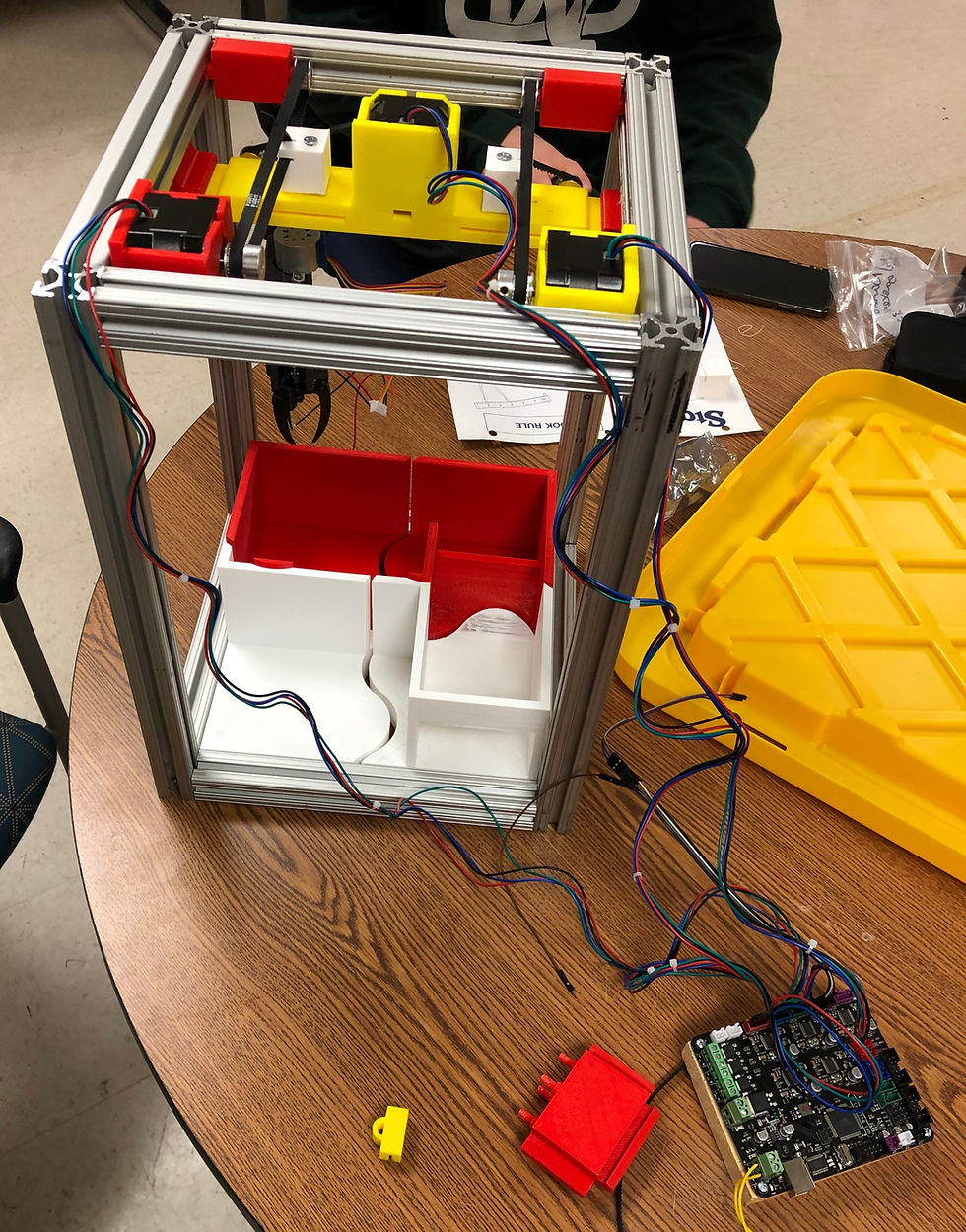
COMPONENTS
The machine's body is made out of aluminum beams that were given to us. Aside from that, all of the pieces for this project were 3D printed using the classroom printers. There were many challenges with this, but the main two were printing time and success. As a group, we experienced many instances where the printers failed during some prints. Because of this, we had to dedicate more time to printing. This was an obvious set-back, but we overcame it in the end.


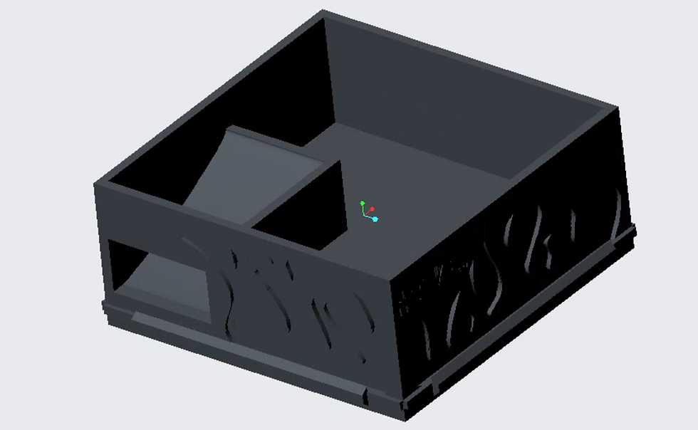
ALL CAD PARTS
In order to 3D print the parts that we needed, we had to make them in CREO Parametrics first. All of the parts were generated using the relative dimensions of the aluminum beams and the motors. Also, the parts were designed to slide into the grooves on the beams to secure them in place and fasten them to the body.


SPECIAL CLAW
Why it is unique
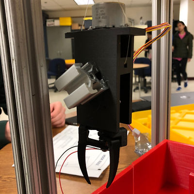
The claw was printed in a Markforged 3D printer. We wanted the claw to be small and strong. It is made from onyx, which is a blend of carbon fiber and nylon. We opted to use this material because it allows for a compact claw with high durability and strength.
FIRST TEST WITH CANDY
This was the moment of truth. All the coding and circuitry had just been completed, and all we had to do was test the claw machine. As shown in the video, it was a success!
THE INTERNALS
Behind the circuitry and code
The claw machine is powered using an arduino and an external DC power supply. The arduino is the MVP os the system. It contains the code to operate the motors and solenoid. Within the code, there is a section dedicated to returning the claw to the shoot so that the user can receive their prize. Moreover, the DC power supply was added because we discovered that we needed more power. An additional 14 Volts of power is added to the system in order to boost the solenoid in the claw and two fans to keep the circuit cooled.

FINAL RESULTS
Looking back, the importance of sticking to a schedule, meeting goals, and engineering design were definitely highlighted. This project was a long endeavor. It took a while for the team to generate a working claw machine because we kept running into issue with 3D printed parts or with the code. However, everything started to come together nicely as we troubleshot and met our defined goals. The showcase was a success, and the guests seemed to enjoy our prototype.
